
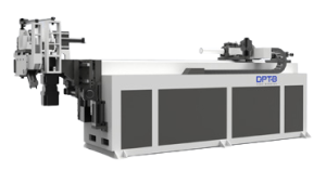

Tube bending machines form metal tubes and pipes into precise curves without welded joints or fittings. Bent tube appears in automotive chassis, HVAC refrigerant lines, aerospace hydraulic assemblies, medical equipment, and structural frameworks — wherever a smooth, controlled curve is stronger and more cost-effective than a jointed alternative.
The challenge is that “tube bending machine” describes a wide family of different technologies. Some machines produce tight precision bends on thin-wall stainless. Others form sweeping architectural curves or handle thick-wall industrial pipe that cannot be bent cold. Choosing the wrong type means poor bend quality, excessive scrap, or a machine that is simply incapable of the work.
This guide covers both dimensions of that decision: the bending method (how the tube is mechanically shaped) and the drive and control system (how the machine is powered, programmed, and operated). Understanding both before evaluating equipment will narrow the field quickly.
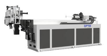
1. Key Components of a Tube Bending Machine
Most rotary-draw-based setups use some combination of the following tooling components. Knowing what each one does makes it easier to understand why certain bends require more complex tooling setups than others.
| Component | Function |
|---|---|
| Bend die | Defines the centerline radius (CLR); the tube wraps around it during the bend stroke |
| Clamp die | Grips the tube against the bend die to prevent slipping |
| Pressure die | Supports the outer wall of the tube and feeds it into the bend zone |
| Wiper die | Positioned at the inside of the bend; suppresses wrinkling as the inner wall compresses |
| Mandrel | Internal support rod inserted before bending; reduces cross-section collapse and ovalization on demanding bends |
Not every bending method uses all five components — ram and compression bending, for example, use none of them in this sense. Bend quality depends on selecting and correctly positioning the right tooling combination for the material, wall thickness, bend radius, and dimensional requirements of the part.
2. The Main Types of Tube Bending Methods
Bending method refers to the mechanical principle used to form the curve. The right method depends on the required bend radius, material, wall specification, and acceptable cross-section deformation. A production environment may run multiple methods on separate machines, each assigned to a specific range of work.
2.1 Rotary Draw Bending
Rotary draw bending is the standard for precision fabrication. The tube clamps to a bend die, which rotates around its axis while a pressure die feeds the tube and supports the outer wall. The centerline radius is fixed by the die — every bend on that die produces the same geometry, which is where the method’s repeatability comes from.
That fixed-CLR characteristic is both a constraint and a practical advantage. Each die is purpose-made for one radius, but once a setup is qualified, part-to-part consistency is built into the tooling rather than dependent on the operator.
Typical applications: automotive chassis and exhaust components, structural handrails, roll cage tubing, HVAC branch fittings, hydraulic line assemblies, fitness equipment frames.
For complex parts with multiple bends at different positions and rotation angles, CNC control handles the sequencing automatically — feeding, rotating, and bending in a programmed cycle without manual repositioning between bends.
2.2 Mandrel Bending
Mandrel bending is rotary draw bending with an internal support. The machine is the same; the mandrel is the addition that extends what the setup can handle.
Without internal support, the inner wall of a tight bend has nowhere to go except inward. On thin-wall tube or aggressive CLR-to-OD ratios, this causes wrinkling on the inside of the bend and flattening on the outside. A mandrel, positioned just inside the bend tangent point, supports the tube wall through the deformation zone.
Two common mandrel types:
- Bullet mandrel — A solid insert with a tapered nose. Handles most structural and exhaust bending applications.
- Ball mandrel — Linked articulating spheres that follow the tube through the bend zone. Used for the most demanding combinations of thin wall and tight CLR.
Whether a mandrel is required depends on several factors working together: CLR-to-OD ratio, wall thickness, material ductility, and the dimensional tolerances the finished part must meet. A low CLR-to-OD ratio increases the risk of wrinkling and ovalization — particularly with thin-wall tubing — but the exact threshold varies with material and tooling setup. A wiper die is often added alongside a mandrel to further suppress inside-radius wrinkling on aggressive bends.
Typical applications: precision exhaust systems, aerospace hydraulic and fuel lines, medical device frames, stainless or high-strength structural tube where cross-section integrity is specified.
2.3 Roll Bending
Roll bending uses three rollers in a triangular arrangement. As the tube passes through, it curves to a radius determined by roller spacing. Unlike rotary draw bending, the CLR is not fixed to a die — it is adjusted by changing the position of the upper or lower roller, and the tube is passed through multiple times until the desired curve is reached.
That adjustability makes roll bending the right method for large-radius sweeps, complete rings, and continuous curves where no fixed-CLR die would be practical. It is also the correct tool for sections too long or too gently curved for a rotary draw setup to handle.
The trade-off is precision and repeatability. Achieving a specific radius is iterative and operator-dependent without sophisticated CNC roller control. For architectural metalwork, furniture, coil forms, and decorative railings, this is acceptable. For structural nodes, documented CLR requirements, or multi-bend parts with tight tolerances, it is not.
Two common variants exist: simple 3-roll bending (bends in a single plane) and Three-Roll Push Bending (TRPB), which adds tube rotation to allow bends to form in different planes from one setup.
Typical applications: architectural and ornamental railings, curved furniture frames, heat exchanger coil tubing, large-radius pipe sweeps in industrial installations.
2.4 Ram Bending
Ram bending uses a hydraulic ram to push a center die into the tube while two stationary side supports resist the movement. As the ram travels, the tube deforms around the center die and takes the bend angle.
The method is mechanically simple and tooling costs are low. The significant trade-off is cross-section deformation: without internal support, the tube ovalizes at the bend zone more than any other method produces. For exhaust repair and muffler shop work — where throughput matters more than tight tolerances and some ovalization is acceptable — this is a practical, cost-effective choice.
For structural tube, precision hydraulic lines, or any part where cross-section roundness, flow area, or wall integrity is specified, ram bending is not appropriate. Applying it outside its intended scope — particularly to load-bearing or structural applications — is one of the more common selection errors in fabrication shops.
Typical applications: exhaust pipe repair, muffler shop work, utility pipe bends where ovalization does not affect function.
2.5 Compression Bending
Compression bending forms the tube by pushing it around a fixed bend die using a moving pressure shoe or swing arm. The bend die is stationary; the tube is fed against it and compressed into shape as the shoe sweeps through the bend arc.
The distinction from rotary draw bending is the motion sequence: in rotary draw, the die rotates and pulls the tube with it. In compression bending, the die is fixed and the tube is pushed around it. This results in more cross-section deformation than rotary draw, but the tooling is simpler and the machine cost lower.
Compression bending is practical for mild-radius bends on relatively ductile material where some ovalization is acceptable, and where the geometry does not require the tight CLR control or multi-bend programmability of a rotary draw setup. It is common in manual and semi-automated benders used for conduit, light structural tube, and simple furniture frames.
Note that machine terminology is not always consistent across suppliers — some manufacturers use “press bender” or “ram bender” for what is functionally a compression bending setup. The distinguishing factor is the tooling motion: if a fixed die form bends the tube and a shoe or arm provides the compressive force, it is compression bending regardless of what the machine is called.
Typical applications: electrical conduit, light structural bends, simple furniture and fixture components, mild-radius bends on ductile tubing.
2.6 Induction Bending
Induction bending is a specialized process for large-diameter, thick-wall pipe — work that is impractical to bend cold due to force requirements or material damage risk. An induction coil heats a narrow band of the pipe at the point of forming while the pipe is pushed through at a controlled feed rate. The heated zone is far more ductile than the surrounding material; bending force is applied there, and the pipe is cooled immediately downstream of the coil to lock in the geometry.
The process can reduce the need for internal tooling on many large-pipe applications, though actual tooling requirements depend on pipe geometry, material grade, bend radius, and process parameters. When heating, feed rate, bending radius, and cooling are properly specified, controlled bends in large-diameter pipe are achievable with good wall-thickness consistency.
Mechanical properties of the finished bend depend on the material grade and the thermal cycle applied. Depending on the specification, post-bend heat treatment or inspection — including wall thickness measurement and dimensional verification — may be required. Induction bending of pressure pipe is subject to specific design and inspection requirements under applicable codes.
Typical applications: oil and gas pipeline fittings and elbows, shipbuilding structural members, large-diameter industrial piping, construction equipment and crane boom sections, power plant piping.
3. Manual, Hydraulic, Hybrid, and All-Electric CNC Tube Benders
Bending method describes how the tube is shaped. Drive and control technology describes how the machine produces and manages that force. The two choices are independent — a rotary draw machine, for example, can be manual, hydraulic CNC, hybrid, or all-electric CNC depending on how it is built and controlled.
The right drive system depends on production volume, bend complexity, required accuracy, operating environment, and the trade-off between capital cost and long-term operating cost.
3.1 Manual Tube Benders
Manual tube benders rely on hand force or a simple lever mechanism. Bending accuracy is entirely operator-dependent — results vary between operators and across shifts, and there is no stored program or automatic angle control.
For low-volume work, on-site maintenance bending, or prototyping, manual machines serve their purpose at minimal capital cost. For any production environment where parts must hit consistent geometry, the operator variability inherent to manual bending creates quality problems that scale with volume.
Best fit for: maintenance and repair work, on-site bending, prototype fabrication, very low volume shop work where cost is the overriding constraint.
3.2 Hydraulic CNC Tube Benders
Hydraulic CNC machines combine hydraulic actuation with CNC programmable control. The hydraulic circuit generates the high bending force needed for large-diameter or thick-wall tube. CNC control adds programmability, multi-bend sequencing, and repeatable execution across production runs.
These machines have been the industrial standard for decades and remain the dominant choice where tube diameter is large, wall thickness is significant, or bending force requirements exceed what current all-electric platforms can deliver at equivalent cost.
Practical trade-offs to factor into procurement:
- Hydraulic oil systems require scheduled maintenance; actual oil consumption depends on machine size, oil volume, change intervals, and leak rate — consult the manufacturer’s maintenance schedule for realistic estimates
- Accuracy at low oil temperatures is reduced; warm-up time is required for consistent production
- Oil contamination risk is a consideration in clean or sensitive production environments
- Aging hydraulic circuits can introduce bending force variability, affecting angle repeatability
Best fit for: heavy-duty structural fabrication, construction machinery components, shipbuilding, large-bore industrial piping, applications where bending force capacity is the primary sizing constraint.
3.3 Hybrid CNC Tube Benders
Hybrid machines combine hydraulic actuation for high-force functions (typically the main bending axis) with servo motor control on positioning axes — feed distance, tube rotation, and clamp/pressure die movement. The hydraulic circuit handles peak bending load while servo axes provide precise positioning.
This configuration is a practical middle ground: the force capacity of hydraulic bending with more precise control over positioning functions than a fully hydraulic system typically delivers. Many production machines in the mid-tier market fall into this category, and some manufacturers market them as CNC hydraulic machines without explicitly labeling the servo-driven axes.
When evaluating accuracy specifications on hybrid machines, it is worth clarifying which axes are hydraulic-actuated and which are servo-driven, as this directly affects positioning repeatability and angle consistency.
Best fit for: medium to high-volume production requiring more positional accuracy than a standard hydraulic CNC provides, without the capital cost of a full all-electric platform.
3.4 All-Electric CNC Tube Benders
All-electric CNC tube benders replace the hydraulic circuit entirely with servo motors — typically one servo axis per machine function. This changes the performance profile in several ways that are relevant to precision manufacturing environments.
Key differences from hydraulic systems:
- Servo-driven axes provide precise, repeatable control of bending angle and positioning; specific accuracy figures depend on machine model and configuration — consult manufacturer specifications
- No hydraulic oil system means no warm-up requirement, no oil-related contamination risk, and reduced maintenance consumables
- Energy consumption is lower per cycle, since servo systems draw power only during active motion rather than running a hydraulic pump continuously
- Integration with MES/ERP, CAD/CAM program import, 3D simulation, and automated loading/unloading is generally more straightforward than with hydraulic platforms
The trade-off is capital cost. All-electric machines carry a higher purchase price than comparable hydraulic models. Whether the operating cost difference justifies the premium depends on annual production volume, energy costs, maintenance labor rates, and scrap rate differences — variables that differ significantly between facilities.
Best fit for: automotive and EV structural components, aerospace hydraulic and fuel line assemblies, medical device fabrication, high-volume precision production, and environments where oil-free operation is required.
4. How to Choose the Right Tube Bending Machine
Equipment selection becomes more straightforward when framed around four questions. Working through them in order narrows the field before comparing specific models or suppliers.
1. What centerline radius is required?
Tight bends — where the centerline radius is small relative to the tube OD — generally require rotary draw bending, and often mandrel support. Large-radius sweeps or continuous curves point to roll bending. When evaluating a bend specification, the CLR-to-OD ratio is a useful early-screening number: a low ratio increases the risk of wrinkling and ovalization, particularly on thin-wall tube, and typically indicates that mandrel tooling should be evaluated. The exact threshold depends on wall thickness, material, and allowable cross-section deformation — it is a starting point for tooling design, not a hard cutoff.
2. What are the wall thickness and material specifications?
Thin-wall tube in stainless steel, aluminum, or high-strength alloys is more prone to wrinkling and collapse at the bend zone, and typically requires mandrel support. Thick-wall, large-diameter carbon steel pipe for structural or pressure service points toward heavy hydraulic CNC or induction bending. Material ductility and yield strength affect springback and the force required to form the bend — these need to be part of the machine sizing conversation.
3. What production volume and repeatability does the job require?
| Production Scenario | Typical Machine Choice |
|---|---|
| Prototypes, maintenance, one-offs | Manual or simple NC |
| Medium volume, standard tolerances | Hydraulic CNC |
| High volume, tight tolerances, automated cells | Hybrid or all-electric CNC |
| Complex 3D geometry, alternating bend directions | All-electric CNC, L/R configuration |
| Large-diameter structural or pressure pipe | Heavy hydraulic CNC or induction |
4. What cross-section quality does the application require?
Structural tube, precision hydraulic lines, and cosmetic or flow-critical parts require a method that controls deformation — rotary draw with or without mandrel. Exhaust repair, conduit, and utility plumbing where some ovalization is acceptable open up ram or compression bending as lower-cost alternatives.
Practical example — thin-wall stainless tube with multiple bends:
Consider a part requiring three bends at a relatively tight CLR in 1.5 mm wall stainless steel, with tight tolerances on bend angle and no visible ovalization. The initial selection logic would be:
- Bending method: rotary draw, with mandrel and wiper die tooling to be confirmed through tooling trials
- Control: CNC, to manage the multi-bend sequence and angle repeatability
- Drive system: hydraulic CNC, hybrid, or all-electric, selected based on production volume, required cycle time, available budget, and whether oil-free operation is necessary for the production environment
Actual mandrel sizing, die clearances, and springback compensation values would be determined from material certification data and tooling trials — not from general guidelines alone.
For tooling setup after machine selection, see our guide on [IL: tube bending tooling solutions] covering die material, CLR options, and mandrel sizing.
5. Tube Bending Machine Applications by Industry
The table below reflects common pairings of industry, bending method, and drive system. They are typical starting points, not fixed answers — within any industry, tube diameter, wall thickness, part complexity, and production volume vary enough that the right specification needs to be evaluated for each application.
| Industry | Typical Parts | Common Method | Key Selection Factors |
|---|---|---|---|
| Automotive & EV | Chassis members, exhaust, seat frames, headrests | Rotary draw + mandrel | Multi-bend geometry, cycle time, angle repeatability, volume |
| HVAC | Refrigerant lines, coil manifolds, fittings | Rotary draw | Tube diameter, wall thickness, bend radius, production rate |
| Aerospace | Hydraulic lines, fuel lines, cabin structures | Mandrel bending | Material spec, surface quality, dimensional tolerance, traceability |
| Furniture & Fitness | Chair frames, handrails, treadmill structures | Rotary draw or roll | Surface finish requirements, tube spec, changeover frequency |
| Construction & Shipbuilding | Structural pipe, crane components, scaffolding | Induction or heavy hydraulic | Pipe diameter, wall thickness, material grade, code requirements |
| Medical | IV poles, operating table frames, mobility aids | Rotary draw | Material, cleanliness requirements, dimensional consistency |
| Oil & Gas | Pipeline fittings, large-bore process pipe | Induction bending | Diameter, wall spec, pressure design code, post-bend inspection |
6. Tube Bending Machine Cost and Total Cost of Ownership
Purchase price is the visible cost. For procurement decisions, total cost of ownership (TCO) over the machine’s service life is the more useful comparison — particularly when evaluating hydraulic against all-electric platforms.
A practical TCO framework covers four cost categories:
Annual Operating Cost= Energy+Maintenance & Consumables+Scrap Cost+Downtime CostAnnual Operating Cost=Energy+Maintenance & Consumables+Scrap Cost+Downtime Cost
For hydraulic machines, the main variables are: hydraulic oil procurement and disposal (quantity and interval depend on machine design — consult the manufacturer’s maintenance schedule), seal and hose replacement as the circuit ages, warm-up time losses per shift start, and any scrap rate attributable to temperature-related bending variability.
For all-electric machines, the main variables are: higher capital cost at purchase, lower energy consumption per cycle (servo systems draw power proportional to load, not continuously), reduced oil-related consumables, and potentially lower scrap rates if the improved angle repeatability reduces out-of-tolerance parts.
Whether the operating cost difference justifies the capital premium depends on the specific production profile: annual machine hours, production volume, local energy costs, maintenance labor rates, and scrap rates. A high-volume three-shift operation reaches a different conclusion than a single-shift facility doing moderate volumes. The calculation should be done with your actual numbers, not industry-level averages.
For manual machines, the cost structure is different again: minimal capital and maintenance, but high labor cost per part and significant quality risk at any meaningful production volume.
7. Common Questions About Tube Bending Machines
Q1: What is the difference between pipe bending and tube bending?
Answer: In engineering usage, pipes are specified by nominal pipe size (NPS) and schedule, and are primarily used for fluid conveyance. Tubes are specified by actual outside diameter and wall thickness, and are more commonly used in structural and precision applications. Most bending machines handle both, but tooling must be sized to the actual OD and wall thickness — a pipe and tube with the same nominal size typically have different actual dimensions, which affects die fit and mandrel sizing.
Q2: When do I need a mandrel?
Answer: A mandrel is needed when the bend geometry would cause the tube wall to collapse or wrinkle without internal support. The main indicators are: a low CLR-to-OD ratio, thin wall relative to OD, materials with high yield strength and limited ductility (such as stainless steel or high-strength alloys), and tight tolerances on cross-section roundness. The specific threshold varies with material and tooling — if a trial bend shows wrinkling on the inside radius or visible flattening on the outside, adding a mandrel is the first corrective step.
Q3: What causes wrinkles on the inside of a bent tube?
Answer: Inside-radius wrinkling occurs when the compressed material on the inner wall has no support and buckles. The main causes are: bending without a mandrel when wall ratio or CLR demands one, a worn or incorrectly positioned wiper die, mandrel tip positioned too far back from the tangent point, and bending speed set too high for the material’s ductility. Wrinkling is a tooling and setup problem — the fix is almost always a tooling adjustment, not a machine change.
Q4: What is the difference between NC and CNC tube benders?
Answer: NC (Numerically Controlled) machines execute preset bending parameters but have limited programmability — typically controlling bend angle only, with manual tube feeding and rotation between bends. CNC (Computer Numerically Controlled) machines control multiple axes (bend angle, feed distance, tube rotation) in a programmed sequence, and can store complex multi-bend programs. The specific capabilities of any machine depend on the controller and configuration; the terms are sometimes used loosely by manufacturers, so it is worth confirming which axes are actually controlled and how the program is created and stored.
Q5: Can one machine handle multiple bending methods?
Answer: Some machines combine capabilities — for example, certain rotary draw platforms accept a roll-bending head as an accessory, and a rotary draw machine with a mandrel attachment covers both standard and mandrel bending. However, ram, compression, and induction bending each require purpose-built equipment. No single machine spans the full range of methods. When a shop needs both large-radius roll work and tight-radius precision bends, two separate machines are the correct answer.
Q6: How does springback affect bend angle, and how do CNC machines handle it?
Answer: Springback is the elastic recovery of the tube after bending force is released — the part springs back toward its original shape, so the actual bend angle is always slightly less than the die position would suggest. The amount depends on the material’s yield strength and elastic modulus; high-strength steel and stainless springback more than mild steel or aluminum. CNC machines compensate by overbending past the target angle by a calculated amount, so the part reaches the correct geometry after springback. Material-specific compensation values are typically established during tooling trials and stored in the machine program for production runs.
8. Conclusion
Selecting the right tube bending machine comes down to two matched decisions: the bending method that suits the geometry and material, and the drive and control system that suits the production volume and accuracy requirement.
Rotary draw bending — with or without mandrel support — covers the majority of precision fabrication work. Roll bending handles large-radius and ring geometry that rotary draw cannot address economically. Ram and compression bending are fast and cost-effective for exhaust and utility work where cross-section deformation is acceptable. Induction bending fills the heavy-industry niche where pipe diameter and wall thickness make cold bending impractical.
On the drive side, hydraulic CNC machines remain competitive for heavy-duty and large-diameter applications. Hybrid and all-electric CNC platforms offer better repeatability, cleaner operation, and lower per-cycle energy costs — at higher initial investment. TCO over the machine’s service life, not purchase price alone, is the comparison that matters for most production environments.
The most productive next step before any purchasing decision is to work through the four selection questions with actual part drawings: required CLR, material and wall specification, production volume and repeatability requirement, and allowable cross-section deformation. Those four answers define the field more reliably than any general specification comparison.