
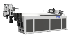

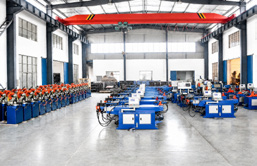
A tube bending machine forms metal tubing into specified angles and radii using mechanical force and dedicated tooling. Depending on the part geometry and production requirements, it may use rotary draw bending, roll bending, ram bending, or other forming methods. Machine selection depends on tube diameter, wall thickness, material, bend radius, dimensional tolerances, and production volume.
More precisely: a tube bending machine permanently deforms a straight metal tube into a specified shape — a defined bend angle at a defined centreline radius — without fracturing the wall or distorting the cross-section beyond acceptable limits. The scope covers shop-fabricated tube assemblies for applications such as automotive exhaust systems, fluid lines, HVAC pipework, furniture frames, and structural components. Large-diameter pipeline field bending is a related but distinct application, with different equipment and constraints.
1. How Does a Tube Bending Machine Work?
Bending a tube is not the same as bending a solid rod. A tube has a hollow cross-section, and that hollow reacts to bending force in two opposing ways simultaneously.
As the tube bends around a radius, the outer wall stretches under tension. At the same time, the inner wall is compressed. Left without support, the compressed inner material buckles inward into a wrinkle; the tensioned outer wall thins and may crack. The machine’s job — through its combination of dies, supports, and drive force — is to manage both extremes at once so the final part holds its shape and meets its dimensional specification.
The general sequence on any tube bending machine follows the same logic:
- Position the tube at the correct bend location.
- Restrain and support it so it cannot shift or collapse during the stroke.
- Apply controlled force to rotate or push the tube around the desired radius.
- Release the tube, which will spring back slightly from the bent position.
- Measure the achieved angle, geometry, and surface condition against the drawing.
The drive source — hydraulic cylinders, electric servos, or manual leverage — changes the precision and repeatability of that force. The bending method changes how the tube is supported and how force is delivered.
1.1 What the dies and mandrel actually do
Rotary draw bending, the most widely used precision method in fabrication shops, uses a coordinated set of tooling that is worth understanding before moving to other methods.
- Bend die: The master die around which the tube forms. Its groove radius defines the centreline radius of the finished bend.
- Clamp die: Grips the tube firmly against the bend die so it does not slip during the bending stroke.
- Pressure die: Tracks alongside the straight section of the tube as it feeds into the bend, supporting the outer wall to limit thinning.
- Wiper die: Positioned at the tangent point on the inside of the bend, it smooths the material as it compresses — helping to prevent wrinkles from forming at the intrados.
- Mandrel: A rod or multi-ball assembly inserted inside the tube before the bend. It supports the inner wall from collapsing, which is particularly important for thin-walled tube or tight-radius bends.
Not every setup uses all five. A thick-walled tube at a generous radius may bend cleanly with only a bend die and clamp. A thin-walled stainless steel tube bent to a centreline radius of 1×OD will generally require careful tooling selection and process validation — a mandrel and wiper die are often needed to control wrinkling and cross-section distortion, but the final tooling configuration should be confirmed against the actual material, wall thickness, bend geometry, and quality requirements. The combination is determined by the part, not assumed from the machine type alone.
2. Springback — the Variable Every Operator Must Account For
After the bending force is released, the tube partially springs back toward its original straight position. This elastic recovery is called springback, and it means the machine must overbend beyond the target angle to achieve the correct final geometry.
The amount of springback varies with material properties, wall thickness, bend radius, cross-section shape, and tooling setup. There is no single universal overbend value that applies across materials and configurations. Rather than working from a fixed number, the reliable approach is to perform a trial bend using the specified material and tooling, measure the achieved angle, and adjust the bending program or setup accordingly. For repeat production, record the compensation values and verify them whenever the material batch or tooling changes.
Springback is not a machine defect. It is a material behaviour, and experienced operators treat it as a standard setup variable to be calibrated, not estimated.
3. Types of Tube Bending Machines and Their Applications
Choosing a bending method is a separate decision from choosing a control system or drive type. CNC, hydraulic, and electric describe how the machine is controlled and powered — not how it bends the tube. The bending method is determined by the machine’s mechanical configuration and how force is applied to the tube. The methods below cover the most commonly specified approaches in industrial tube fabrication; other methods such as freeform bending exist for specialised applications and are not covered here.
| Method | How It Works | Typical Application |
|---|---|---|
| Rotary draw bending | Tube is clamped to a rotating bend die and drawn around it | Tight-radius bends, repeatable parts, multi-bend assemblies |
| Roll bending | Rollers progressively form the tube into a curve | Large-radius arcs, rings, coils, architectural profiles |
| Ram bending | A hydraulic ram presses the tube against supporting dies or rollers | Simpler bends where greater cross-section distortion is acceptable |
| Compression bending | A follower die presses the tube around a fixed bend former | Simple, repeatable bends with less demanding distortion requirements |
Rotary draw bending is the dominant method for precision tube fabrication. The tube is clamped to a rotating bend die and drawn around it in a controlled stroke. With correct tooling, it produces repeatable bends at tight radii. It also handles multi-bend parts — where the tube must be repositioned between bends to form geometry in different planes — making it the standard choice for automotive, HVAC, and fluid-line assemblies.
Roll bending is the right choice for large-radius curves, coils, and rings where the radius would be impractical to achieve on a rotary draw machine. The tube passes progressively through a set of rollers, with one adjustable roller increasing the curvature with each pass. It is generally less suited to tight radii or thin-walled tube that requires full inner-wall support.
Ram bending applies direct hydraulic force through a single-point die against two fixed counter-supports. It is the oldest and most accessible method, with low tooling cost, but provides the least support to the tube’s cross-section during bending. Some ovality is inherent to the process. For structural applications where a defined amount of flattening is acceptable — handrails, mild steel frameworks, agricultural equipment — it remains a practical and economical choice.
Compression bending uses a fixed bend former while a follower die moves around it to press the tube into shape. It suits straightforward geometries with less demanding distortion requirements, and is commonly found on dedicated tooling setups for high-volume simple parts.
A note on CNC: a CNC-controlled machine programs and executes the bending stroke digitally, controlling feed length, tube rotation, and bend angle through servo-driven axes. It is not a bending method — it is a control system that can be applied to rotary draw, roll, or other bending configurations. The practical advantage of CNC is repeatable positioning across multi-bend parts and fast changeover when bending programs are stored.
4. What Determines Whether a Bend Is Feasible?
Before selecting a machine or placing a tooling order, the part drawing and material specification need to be reviewed against the bending process. The factors that define feasibility are consistently the same:
- Material and condition: A tube’s elongation percentage matters more than its tensile strength for bendability. Annealed copper bends at very tight radii without internal support; the same tube in a work-hardened condition may crack at the same radius. Mild steel, stainless, aluminium, and titanium all behave differently, and even the same alloy in different temper conditions can produce measurably different springback and formability.
- Outer diameter (OD) and wall thickness: The D/t ratio — outside diameter divided by nominal wall thickness — is a useful screening parameter for estimating how much support a tube is likely to need during bending. A higher D/t indicates a relatively thin wall, which is generally more susceptible to collapse and wrinkling. However, D/t is not a standalone pass-or-fail criterion: minimum bend radius, material ductility, cross-section shape, and tooling support must also be considered when determining the actual tooling configuration.
- Centreline radius relative to OD: Expressed as a multiple of the OD, this is the single most telling dimension on a tube fabrication drawing. A 2×D centreline radius is achievable in mild steel with straightforward tooling in most cases. A 1×D radius in thin-walled stainless requires careful tooling selection and process validation, as described in the tooling section above.
- Bend angle and number of bends: High-angle bends (180° hairpin bends, for example) extend the time the material is under compressive stress. Multiple bends in different planes require controlled indexing between bends — which is where CNC becomes a production necessity rather than a convenience.
- Available straight lengths between bends: Every bending process requires a tangent length — a minimum straight section between the start of a bend and adjacent features or other bends. When bend spacing is tight, tooling and the geometry of the previous bend may physically conflict. This is one of the most common feasibility problems in complex tube assemblies and should be reviewed before tooling is ordered.
- Dimensional tolerances and surface requirements: A structural tube bent to a generous angular tolerance is a straightforward application. A precision fluid-line component requiring tight angle, position, and surface quality in multiple planes is a CNC application with fully qualified tooling and controlled process parameters.
If any of these variables are uncertain, the right step before machine selection is a feasibility review with the intended equipment supplier — send the drawing, the material data sheet, and the expected production volume together.
5. What Can Go Wrong During Tube Bending — and How Is It Checked?
Good bending equipment does not automatically produce good bends. Setup, tooling condition, and material variation all affect results. The defects that appear most frequently in tube fabrication are:
Wrinkling at the intrados (inside of the bend) occurs when the compressed inner wall buckles rather than deforming smoothly. Causes include insufficient or incorrectly positioned mandrel support, a bend radius tighter than the material and tooling combination can sustain, worn or undersized tooling, or inadequate lubrication. Wrinkling is primarily a consequence of compressive deformation that exceeds the material’s ability to deform smoothly in the absence of adequate support.
Wall thinning or cracking at the extrados (outside of the bend) results from tensile deformation exceeding what the material and process can accommodate. The risk increases with tight bend radii, relatively thin walls, limited material ductility, and unsuitable tooling or setup. Inspection should focus on the specified minimum wall thickness and any cracking acceptance criteria in the part drawing.
Ovality — the cross-section becoming elliptical rather than round — is a natural consequence of bending and is always present to some degree. The question is whether the finished part’s ovality falls within the drawing tolerance. For fluid-carrying tubes or those requiring a sealing fit, even small ovality can be a functional concern.
Springback variation is a process stability issue. If the springback compensation is set correctly for one material batch but the next batch has a slightly different yield strength or temper, angle consistency will drift. First-piece inspection at the start of each new material batch is a standard production discipline for this reason.
Cracks at or near the bend indicate either that the minimum bend radius for the material has been exceeded, or that the material condition is not what was specified. Locally harder zones in incorrectly stored or previously worked material can crack without warning even when the setup is otherwise correct.
5.1 What to inspect after bending
A first-piece inspection after setup should check:
- Achieved bend angle (compare to drawing requirement plus recorded springback compensation)
- Centreline radius (check with a radius gauge or CMM on precision parts)
- Ovality at the intrados and extrados relative to drawing tolerance
- Wall condition — visual and tactile check for wrinkling, scoring, and surface damage
- Straight-section dimensions — overall length, tangent lengths, and bend location positions relative to drawing reference points
- On thin-walled tube: wall thickness at the extrados using a tube micrometer or ultrasonic gauge
Pass or fail is determined by the drawing, not by the machine’s nominal capability. Keeping a record of springback compensation values, tooling configurations, and lubrication used for each part number shortens setup time significantly when the job recurs.
6. How to Choose a Tube Bending Machine for Production
Selection starts with the bending method, not the control system. Once the method is clear, the control and actuation choices follow from the production requirements.
Step 1 — Identify the required bending method using the geometry and quality criteria above. Complex, multi-plane tube assemblies in thin-walled material point to rotary draw bending. Large-radius arcs in structural sections point to roll bending. Simple, single-plane bends in heavier-wall tube where some cross-section distortion is acceptable may be suited to ram or compression bending.
Step 2 — Determine the required control level. A single-bend part in one material at one radius can be produced efficiently on a manual or NC machine. A part with multiple bends in different planes, held to tight angular and positional tolerances, is a CNC application — not because CNC is generically superior, but because manual indexing at that complexity level is too slow and inconsistent for production. On a CNC tube bender, the control system manages feed length, tube rotation between bends, bend angle, and springback compensation — all of which can be stored as a program and recalled for repeat jobs.
Step 3 — Consider actuation. Hydraulic drive delivers high force with a robust mechanical arrangement, making it well established for larger-diameter and heavy-wall tube. Electric servo drive offers faster cycle times, lower energy consumption at partial load, and cleaner operation in environments where hydraulic fluid is a contamination concern. The right choice depends on the tube sizes, wall thicknesses, and production volumes involved — not on a generalisation about which technology is better.
Step 4 — Review tooling availability and serviceability. A technically capable machine from a supplier without local tooling stock or field service support will cost more to operate over its lifetime than a more modest machine backed by strong after-sales infrastructure. Tooling lead times, die replacement costs, and local technical support should all be part of the purchase evaluation.
Step 5 — Send a representative drawing for feasibility confirmation. Before finalising any machine purchase, provide the equipment supplier with the most demanding part in your expected mix: the smallest radius, the thinnest wall, the most bends, the tightest tolerance. Provide the actual tube OD, wall thickness, material grade and condition, required centreline radius, bend angles, straight lengths between bends, dimensional tolerances, and expected production volume. A competent supplier will advise whether the proposed machine and tooling combination can produce that part to specification — and what the setup and cycle time implications are.
If you are ready to discuss your application, request a tube bending machine quotation and include the drawing and material specification in your enquiry.
7. Common Questions About Tube Bending Machines
Q1: Is a tube bender the same as a pipe bender?
Answer: The terms overlap in everyday use, but they are technically distinct. Tube is sized by outside diameter and wall thickness and held to tighter dimensional tolerances. Pipe is sized by nominal bore, with OD and wall thickness defined by schedule. Most industrial tube bending machines handle both, but tooling — particularly die groove diameter — must match the actual OD of the material being bent, not a nominal bore designation. Always provide the actual OD and wall thickness when specifying tooling or requesting a quotation.
Q2: Does every bend require a mandrel?
Answer: No. Whether a mandrel is needed depends on the D/t ratio (outside diameter divided by wall thickness), the specified centreline radius, the material, and the required cross-section quality. Thick-walled tube at a generous radius often bends cleanly without internal support. Thin-walled tube at a tight radius frequently requires a mandrel — and often a wiper die as well. The tooling requirement should be established during the feasibility stage, not discovered during the first production run.
Q3: Is CNC a bending method?
Answer: No. CNC (Computer Numerical Control) describes how the machine is programmed and controlled. It manages feed length, tube rotation, bend angle, and other process parameters through servo-driven axes. A CNC machine can perform rotary draw bending, roll bending, or other methods depending on its mechanical design. The bending method is determined by the machine’s tooling configuration and how force is applied — not by whether the machine has a CNC control system.
Q4: What causes a bend to be out of angle tolerance?
Answer: The most common cause is incorrect springback compensation — either because it was not established accurately for the current material batch, or because material properties vary between batches. Other causes include tube slipping in the clamp die, worn tooling with excessive clearance, and inconsistent tube positioning before the bend stroke. Running a first-piece trial at the start of each production run, and recording the springback compensation used, is the most reliable way to maintain angle consistency.
Q5: Can a tube bending machine bend square or rectangular tube?
Answer: Yes, with tooling profiled to match the cross-section. Square and rectangular hollow sections require specially profiled dies to support the corners during bending. Beyond wall thickness, bend radius, and corner radius, the feasibility assessment for square or rectangular tube should also consider bending direction, section orientation, acceptable corner deformation, and whether internal support is permitted. Square tube is not simply a round tube with a different die — the interaction between the flat faces, corner radii, and compressive forces creates different constraints that need to be assessed for each geometry.
Q6: What materials can a tube bending machine bend?
Answer: Steel, stainless steel, aluminium, and copper are the most commonly processed materials. Titanium, brass, and various alloy steels are also bent in specialised applications. The achievable bend radius, required tooling, and process parameters all depend on the material’s ductility, yield strength, and temper. The same machine may produce clean bends in mild steel at a given radius and require completely different tooling or process conditions to achieve the same geometry in stainless or hard-temper aluminium.
Q7: What information is needed to select a tube bending machine?
Answer: To give a meaningful equipment or process recommendation, a supplier will need: tube OD, nominal wall thickness, material grade and temper, required centreline radius, bend angles, number of bends per part, straight lengths between bends, dimensional tolerances, required surface finish, and expected production volume per shift or per year. The more completely this information is provided upfront, the more accurate the machine recommendation, tooling specification, and cycle time estimate will be.
8. Conclusion
A tube bending machine’s value is in its ability to produce a specified curve in a single operation — no welds, no fittings, no assembly joints at the bend location. Whether that operation uses rotary draw bending, roll bending, ram bending, or another method depends entirely on the part drawing and what it demands geometrically.
The selection sequence is straightforward in principle: identify the bending method the part geometry requires, determine the control level and actuation type that match the production volume and complexity, and confirm the full tooling configuration against the actual material and quality requirements. For anything outside routine bends in common materials, the most useful step before purchasing equipment is to send the drawing, the material data sheet, and the production volume to the intended supplier and ask for a feasibility review. That conversation surfaces constraints — on minimum radius, tooling clearance, and straight-length requirements — that no product specification sheet will mention.